
Catch hot joints early
Cable joints and terminations are a common origin of faults in urban networks; continuous monitoring flags heat-driven deterioration before it becomes a failure.
Philippines · Self-powered wireless thermal monitoring
Self-powered from ≥1 A (or 10-year battery for low-current points), ±0.2 °C (−10 to +65 °C), clamp-on installation during a planned outage. Detect overheating joints and ageing cable terminations early — the mechanism behind substation fires — for condition-based maintenance on Meralco and NGCP-class assets.
Why VTI for the Philippines
Cable joints and terminations are a common origin of faults in urban networks; continuous monitoring flags heat-driven deterioration before it becomes a failure.
Wireless, self-powered, clamp-on — suited to retrofit programmes on ageing 34.5 kV air-insulated switchgear and cable terminations.
Energy harvesting from ≥1 A of primary load current with no batteries to replace — zero maintenance trips across thousands of monitoring points.
Compliance & trust
What a Meralco/NGCP due-diligence team should expect — current status shown honestly.
ISO 9001 / CE used to pursue a fast-track approval path for industrial IoT devices; status available on request.
Alignment with PEC (Philippine Electrical Code) installation practice for switchgear-mounted monitoring.
GW22-D outputs Modbus TCP or MQTT; the VTI platform delivers IEC 60870-5-104 to SCADA/HMI. (IEC 61850 not a current capability — on roadmap.)
LoRa AS923 with <1% duty cycle and LBT, aligned to NTC free-band rules.
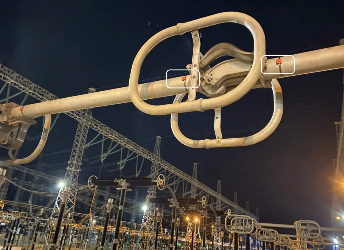
Figures below are taken directly from the VTI-TS-26 and GW22-D datasheets (no representative values).
| Sensor — VTI-TS-26 | Specification |
|---|---|
| Self-powered start current | ≥ 1 A primary load current (harvested directly from the conductor) |
| Accuracy | ±0.2 °C (within −10 to +65 °C) |
| Measurement range | −40 to +125 °C |
| Operating temperature | −40 to +85 °C · humidity 0–100% |
| Working voltage environment | Up to 500 kV (UHV) |
| Wireless | LoRa AS923 band · EIRP 14–22 dBm · duty cycle <1% · LBT (Listen-Before-Talk) |
| Range | Up to 3 km, unobstructed urban environment |
| Sampling | Adaptive 5–30 min (faster as temperature changes) |
| Mounting | Magnetic straps + stainless-steel ties; installed de-energised (isolated, earthed, proved dead) |
| Gateway — GW22-D | Specification |
|---|---|
| Architecture | Receive-only listening hub (does not interfere with the transmission system) |
| Wireless | Dual-band 2.4 GHz (BLE) + LoRa AS923 |
| Capacity | Rated up to 1,000 sensors; practical number set by radio survey (9–38 per gateway in delivered projects) |
| Network & protocols | RJ45 Ethernet 10/100 · Modbus TCP (GW22-D-MODBUSTCP) or MQTT (GW22-D-MQTT) → SCADA / HMI / Cloud; IEC 60870-5-104 via the VTI platform |
| Power | 220 V AC/DC universal |
| Form factor | 93 × 84 × 24 mm, 200 g, DIN-rail / wall mount · −40 to +85 °C |
Note: data integration is via Modbus TCP or MQTT at the gateway, and IEC 60870-5-104 via the VTI platform (IEC 61850 is not a current gateway capability — on the roadmap). LoRa AS923 frequency plan is configurable per country — confirm the regional sub-band before deployment.
Tell us about your substations — we will send the VTI-TS-26 / GW22-D datasheets and a capability profile for evaluation.
[Philippine distribution / integration partner — to be appointed]