Operations engineers
Live hot-spot alarms and load-correlated trends to act before a joint becomes a fault — without de-energizing.
Self-Powered Wireless Thermal Monitoring
VTI builds battery-free, self-powered wireless temperature sensors (VTI-TS-22 / VTI-TS-26) that continuously measure the real hot spots — busbar joints, switchgear contacts, cable terminations and 110–500 kV line connectors — and feed them into your condition-based and risk-based maintenance programs.
Who it's for
VTI sensors are specified by the people accountable for grid uptime and safety. Each role gets a different value from the same continuous temperature stream.
Live hot-spot alarms and load-correlated trends to act before a joint becomes a fault — without de-energizing.
Real thermal behaviour of connections and ratings to validate designs, retrofits and dynamic line rating (DLR).
Early detection of overheating contacts cuts arc-flash and fire risk on energized switchgear and lines.
Objective asset-health data to move from time-based servicing to CBM/RBM and defensible capex decisions.
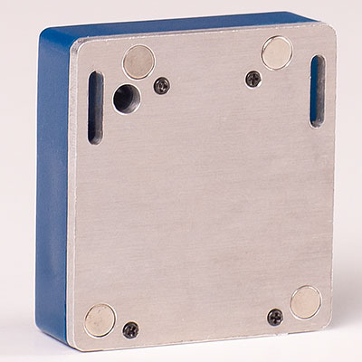
Sensors
The VTI-TS series harvests energy from the conductor's own magnetic field — no battery to replace, no auxiliary supply, no wiring. Each unit measures the contact-point temperature it is clamped to and transmits over an EMI-immune wireless link to a VTI gateway.
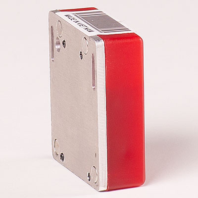 Switchgear & busbar
For busbar joints, isolator contacts and cable lugs in MV/HV switchgear. Battery-free, clamp-mounted on energized conductors.
 Transmission & distribution
Long-range outdoor unit for line splices, dead-ends and lug landings, with a sealed UV-stable enclosure for harsh field conditions.
*Representative values; final figures per product datasheet. Request the datasheet →
From data to maintenance strategy
Time-based servicing either over-maintains healthy assets or misses degrading ones. Continuous temperature is one of the strongest leading indicators of connection failure — the input CBM and RBM need.
Trigger maintenance on actual condition, not the calendar. Rising contact temperature at a given load flags loosening or oxidation early, so crews intervene only when needed.
Combine probability of failure (thermal trend severity) with consequence (asset criticality) to rank work by risk — aligning crews and capex with ISO 55000 asset management.
Temperature-vs-load trending builds an objective health signal per connection point, supporting hot-spot detection, ampacity decisions and end-of-life planning.
Self-powered sensor measures contact temperature on the energized asset.
EMI-immune wireless link to a gateway aggregating up to 1,000 points.
Temperature-vs-load trends, thresholds and alarms feed CBM/RBM logic.
Work orders ranked by risk; intervene before failure, avoid outages.
Read the full technical guide: CBM & RBM with thermal data →
Applications
From a single switchgear panel to a national fleet and a full transmission corridor — covering every connection where resistance, load and ageing create heat.
Circuit-breaker contacts, busbar joints and cable terminations in MV/HV switchgear — the most common thermal failure points.
Bushings, disconnectors and unmanned substations — online temperature/humidity with no cap on sensors or sites.
Splices, dead-ends and lug landings on 110–500 kV lines — hot-spot detection and inputs for dynamic line rating.
Stream point-temperature into SCADA/DMS and asset-management platforms for fleet-wide visibility.
Fiber-optic DTS for buried/long-run cables — a continuous thermal profile alongside point sensors.
Plant switchrooms, large industrial loads and data-center power rooms where downtime is costly.
Platform
Sensors are half the system. VTI ties every measurement point into one platform so operators and asset managers see the whole network on one screen and push data downstream.

Multi-channel concentrator collecting up to 1,000 sensors and forwarding to your server over the network of choice.
Browser dashboards, configurable thresholds, alarms and historical trends — no limit on sensors per site or sites per fleet.
Fiber-optic DTS for power cables, plus IEC 61850 / SCADA integration for smart-substation environments.
Standards & integration
VTI monitoring is designed to slot into the standards and systems grid owners already run.
HV switchgear & assemblies — temperature-rise context for switchgear monitoring.
Switchgear ratings and allowable temperature limits for contacts and connections.
Substation communication for digital, smart-grid integration of sensor data.
Asset-management framework that CBM/RBM thermal data directly supports.
Industries
Anywhere high-current connections must be watched for overheating — from national grids to plants and digital infrastructure.
Substations, switchgear and 110–500 kV lines for transmission and distribution operators and grid owners.
Steel, cement, paper and chemical plants — large loads, distribution boards and busbars under high thermal duty.
Wind/solar collector substations, inverters and connection cabinets — outdoor joints that age fast under weather and cycling.
Fire- and explosion-risk areas where early hot-spot detection is critical to safety and uptime.
Power rooms and distribution (MSB/PDU) where any outage is extremely costly and 24/7 thermal monitoring is expected.
Metro, electrified rail and traction substations — heavily loaded switchgear and busbars with frequent switching.
FAQ
Contact temperature, normalized against load current, is a leading indicator of connection degradation (loosening, oxidation, undersized joints). CBM uses rising temperature-at-load to trigger intervention on actual condition; RBM combines that probability-of-failure signal with asset criticality to prioritize work by risk, in line with ISO 55000.
It harvests energy from the magnetic field of the current in the monitored conductor, powering measurement and the wireless transmitter. There is no battery to replace and no auxiliary supply — important for thousands of points across a fleet.
Yes. The wireless link and electronics are engineered to reject the electromagnetic interference present in high- and ultra-high-voltage fields; VTI-TS-26 is validated for networks up to 500 kV.
Yes — units are clamp-mounted on energized busbars, joints and conductors (live-line), so monitoring is added without de-energizing or scheduling downtime.
A VTI gateway aggregates up to 1,000 sensors and forwards data to your server; the platform supports IEC 61850 / SCADA integration so temperature and alarms reach your DMS and asset-management tools.
Point sensors (VTI-TS) target discrete contact points — joints, terminations, splices. DTS uses fiber to profile temperature continuously along a cable, ideal for buried/long runs and dynamic rating. VTI offers both on one platform.
Tell us about your switchgear, substations or transmission lines and our engineers will scope the right sensors, gateway and integration — and send full datasheets.